
Cubit Mesh#
Geometry#
We construct the geometry by taking a horizontal cross-section of a 3D block. Alternatively, we could have constructed the geometry by building it up from points and curves like we did with Gmsh. Fig. 78 shows the geometry and variables names of the vertices and curves.

Fig. 78 Geometry created in Cubit for generating the finite-element mesh. The names of the vertices and curves match the ones we use in the Cubit journal files.#
Meshing using Python Script#
Note
New in v4.1.0.
We use a Python script to generate the mesh rather than Journal files. We also use the skeleton sizing function for the surface.
We use the Python script generate_cubit.py to generate the mesh.
The Python script is setup so that it can be run from within Cubit or as a standalone Python script without the Cubit GUI interface.
In this example, we will run the script from within Cubit using the Journal editor.
Open the Python script generate_cubit.py in the Cubit journal editor.
Play the selected script or play the lines, making sure you play the first line so that Cubit uses the Python interpreter when running the script.
We specify the parameters controlling the geometry, mesh size, and cell shape near the top of the script.
We create a brick, extracting a midsurface from it, and then splitting the remaining surface with an extended fault and a splay surface. We assign names to the surfaces, curves, and important vertices that we use when we specify the mesh sizing information and defining blocks and nodesets.
Important
We use IDless journaling in Cubit. This allows us to reference objects in a manner that should be independent of the version of Cubit that is being used. In the Python script the original command used is typically commented out, and the following command is the equivalent IDless command.
Important
In addition to providing nodesets for the fault and splay, it is also important to provide nodesets defining the buried edges of these two surfaces. In 2D this consists of a single vertex for each surface. This information is required by PyLith to form the corresponding cohesive cells defining fault surfaces.
Note
We use the skeleton sizing function to gradually increase the cell size with distance from the fault. This is much simpler than applying the bias sizing function to the curves and surfaces. We set the minimim size equal to the cell size on the fault and the maximum gradient equal to the “bias”.
Once you have run the Python script to construct the geometry and generate the mesh, you will have a corresponding Exodus-II file (mesh_tri.exo or mesh_quad.exo).
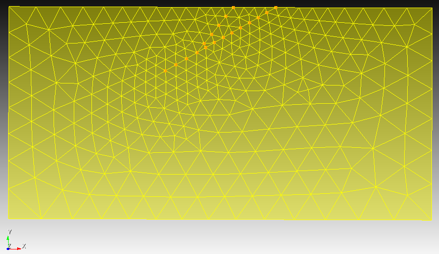
Fig. 79 Finite-element mesh with triangular cells generated by Cubit.#

Fig. 80 Finite-element mesh with quadrilateral cells generated by Cubit.#