
Gmsh Mesh#
We use Gmsh to generate the finite-element mesh.
Due to its size, we do not include the finite-element mesh in the PyLith source or binary distributions.
See the instructions in the input/README.md file for how to download the mesh produced by Gmsh.
Overview#
We use contours of the Cascadia Subduction Zone from Slab v1.0 [Hayes et al., 2012] for the geometry of the subduction interface.
We define the top surface using topography and bathymetry from Etopo 2022 [NOAA National Centers for Environmental Information, 2022].
The data files cas_contours_dep.in.txt.gz and etopo2020_bedrock_local.nc provide the subduction interface contours and the topography and bathymetry, respectively.
The Python script generate_gmsh.py reads in the subduction interface contour files and the topography and bathymetry grid file, constructs the geometry, marks the boundaries, fault surfaces, and materials, and generates the finite-element mesh.
Tip
We define the coordinate systems we use in the simulations in the Python script coordsys.py to make it easier to convert to and from various georeference coordinate systems in the pre- and post-processing.
PyLith will automatically convert among compatible coordinate systems during the simulation.
generate_gmsh.py. If you do not want to generate the finite-element mesh, refer to the instructions in input/README.md on how to download the Gmsh file.#$ ./generate_gmsh.py --write --filename=mesh_tet.msh
Geometry#
We construct the geometry with the following steps:
Construct basic building blocks.
Load the topography and bathymetry values and construct a surface.
Load the subduction interface contours and construct a surface.
Calculate the average surface normal for the top of the slab.
Construct the bottom of the slab and build a volume for the slab.
Construct a splay fault using the slab interface contours.
Construct a box for the domain.
Construct a surface corresponding to the continental Moho.
Combine the basic building blocks.
Chop off the top of the domain using the topography and bathymetry surface.
Fragment the domain with the slab volume.
Fragment the domain with the splay surface to create a wedge.
Fragment the domain with the continental Moho surface.
Create a patch for the subduction interface and fragment the domain with it.
Get tags of the various surfaces for use in marking boundaries, faults, and materials.
Mark boundaries, faults, and materials#
Create material groups for each volume to make it easy to assign different material properties to each one.
Create boundary groups corresponding to boundary conditions and faults.
Generate the mesh#
We create a cell size field to increase the discretization size with distance from the top of the subduction interface. We generate the mesh and then use Gmsh mesh quality tools to improve the shape of the cells.
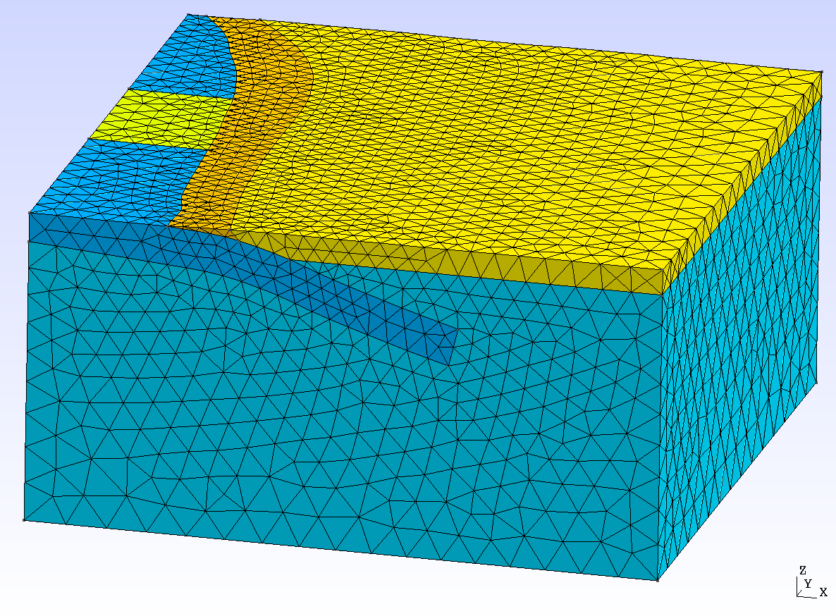
Fig. 145 Finite-element mesh with tetrahedral cells generated by Gmsh.#