
Cubit Mesh#
Geometry#
We construct the geometry following the same general procedure that we used with Gmsh. We first create points, then connect the points into curves, and finally connect the curves into surfaces. Fig. 132 shows the geometry and variables names of the vertices and curves.

Fig. 132 Geometry created in Cubit for generating the finite-element mesh. The names of the vertices and curves match the ones we use in the Cubit journal files.#
Meshing using Python script#
Note
New in v4.1.0.
We use a Python script to generate the mesh rather than Journal files. We also use the skeleton sizing function for the surface.
We use the Python script generate_cubit.py to generate the mesh.
The Python script is setup so that it can be run from within Cubit or as a standalone Python script without the Cubit GUI interface.
In this example, we will run the script from within Cubit using the Journal editor.
Warning
In this example we do not use IDless journaling in Cubit.
The ids of some of the geometric entities might be depend on which version of Cubit you are using.
The differences are most likely to occur when we split curves.
For example, the section of the curve labeled c_topo might be labeled c_topo@A in your version with similar permutations for other curve sections.
Note
We use the skeleton sizing function to gradually increase the cell size with distance from the fault. This is much simpler than applying the bias sizing function to the curves and surfaces. We set the minimim size equal to the cell size on the fault and the maximum gradient equal to the “bias”.
Once you have run the Python script to construct the geometry and generate the mesh, you will have a Exodus-II file (mesh_tri.exo).
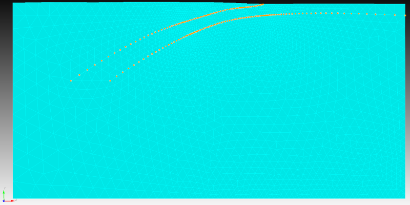
Fig. 133 Finite-element mesh with triangular cells generated by Cubit.#